Guidelines for Images to be used for Photogrammetry
January 1, 2021 version
By Ken Merryman
Disclaimer: First let me say we are also in a learning mode and there are a million combinations of variables that affect the QOR, quality of results. We have gone down a path that works but that is not to say there aren’t many other paths that work and may work better. Hopefully by collaborating with other contributors we can evolve a more robust set of guidelines.
Software: The archaeology industry seemed to standardize on the Agisoft Photoscan (now Metashape) probably because it was first to market. Our experiments show it is very capable of doing quality underwater models. The NPS SRC started with Agisoft, but is using Reality Capture now also. In our tests we have found Reality Capture to be much faster, but less able to reliably knit together all of our less than optimal underwater images leaving many components or pieces of the model that must be manually aligned. Jerry Eliason and I have been using 3D Flow’s 3D Zephyr software. It also does a good job of assembling less than optimal underwater images but is much slower than Agisoft or Reality Capture.
Background: Our GLSPS team has been experimenting with photogrammetry for five years shooting with three different cameras and multiple lighting configurations. We have used a Jerry Eliason Sony surveillance drop camera which shoots 1080×1920 HD images (Manasoo and J.H. Jones, Hesper). I shot with an older Sony Z1U camcorder 1080×1440 (Strathmore, Silver Lake, Comet) and later a Canon 5D Mark IV at 1080×1920 video (Strathmore, Hopkins) then later 6720×4480 30megapixel images (Hopkins). Brett Seymour with the NPS shoots 40 megapixel images for the parks models. Imaging expert Evan Kovak has a multiple camera imaging system mounted on a scooter which records images from multiple angles. He shoots Nikon mirrorless 40 megapixel cameras. Tim Pranke has been using a two-camera rig with GoPro4’s shooting HD video with success. All configurations have worked to some extent. We have also tried processing older standard definition photomosaic video with varied results (Sophie’s Wreck, Chisholm Cumberland Site).
Video or Stills: The software can handle either but basically it picks individual frames at a rate you select out of the video. The software varies on the video formats they can handle, but formats can usually be converted. Agisoft is very limited on which video formats it can process but Reality Capture does multiple video formats. When using video we have used .mp4. When using stills we have used .jpg or RAW. We used 30 megapixel jpegs for a while. Brett Seymour of the NPS Submerged Resource Center uses RAW stills which can be color adjusted better before processing. It takes either very fast storage media or multiple cards to keep up with the write speed for storing high resolution RAWs at more than one per second. My Canon shoots 3 images per second with jpeg and I swim at a normal rate. Brett shoots at one image per second and swims slowly. If you choose to adjust color or exposure in Photoshop or Lightroom or other software you will probably want to be able to apply the same corrections to all images in a batch process. I have batch adjusted exposure in Photoshop and it seemed to work well. When I adjusted exposure on some of the underexposed individual frames to get the software to use them, it had the opposite affect rejecting those frames and the subsequent frames. I have evolved to using 30 megapixel RAW images now too. The availability and flexibility in adjusting the quality of the images in Photoshop and being able to use the Dehaze filter seems to give much better starting quality of images. I now set my time-lapse photo rate at one per second for most of the pass. When I make a turn or pan on some detail if I hit the shutter button the camera will shoot at 3 frames per second for a short time burst which allows me to connect passes more reliably.
Resolution: What we learned was HD 1080×1920 does work well but when the models are compared to models shot with higher resolution cameras the difference is obvious like any time you compare two images shot at different resolutions. The lower resolution image looks good until you look at it side by side with a higher resolution image. We were originally concerned about added processing time for the higher resolution images but it turned out not to be a problem. It did use more memory when processing the 30 megapixel images vs. the HD images but the surprisingly the processing time in the software we are using 3D Zephyr and Agisoft did not increase significantly. The relative performance insensitivity to the higher resolution images may be due to the fact that at least Agisoft downgrades the resolution before aligning the images. The user does have control over the amount it downgrades the images. I would recommend at least shooting 4k images but HD does work. We have evolved to using 30 megapixel RAW images since they can be adjusted better than the .jpg and the higher resolution tends to give more feature points to align.
Depth of Field: Good depth of field is important as it gives the software more in-focus area in the image and therefore more feature points to align so using a smaller aperture will help.
Lighting: Even soft lighting is best. Strong shadows will obscure parts of the model. Try to make your artificial light soft and evenly distributed across the image plane. Remember if you use a very wide angle lens you need to be able to light the area you are covering with the lens, otherwise you are losing useful image area needed to create the feature points. Either natural or artificial lighting work, but if you are shooting a shallow wreck with a large gradient of lighting across the wreck site like a wreck on a steep slope or plan to shoot on multiple days with highly variable conditions using artificial light will give you more control over the lighting. Shooting on a night dive may solve those problems. If you are shooting stills, using a strobe that will cycle at the rate you want to shoot is a good way to go. I use powerful LED video lights and that also works.
Lens Length: We have gained a bit of experience since the last version of these guidelines. Both Agisoft and 3D Zephyr software recommends not using too wide of a lens. We originally stuck to an equivalent 20mm with dome port. Since then after recommendations from Marcus Blanchford who is one of the leaders of the Truck Lagoon Baseline project we have tried using wider angle lenses with great success. There are a number of advantages to using wide angle lenses underwater. Of course getting closer always give you less distance in the water column and clearer images. Also theoretically the photogrammetry algorithm which determines in space where each point in your image lies has less uncertainty when using images shot with wider angle lenses. You cover more of the wreck on each pass which allows fewer passes and better overlap. A fisheye lens behind a dome port will allow you to focus on the virtual image and yields a depth of field from some near point to infinity with a larger aperture so you need less light. A rectilinear lens straightens out the curved lines of a fisheye lens but needs a smaller aperture to give the same depth of field. I’ve used both and both work, but the rectilinear lens does require more light. I have shot with a 16mm rectilinear lens and a 15mm fisheye – both are zoom lenses. I shoot with the narrowest setting of my 8mm-15mm fisheye lens to avoid vignetting of the image or the widest setting of the 16mm to 30mm rectilinear lens. It is important to be consistent for the whole shoot. Pick one lens and stick to it. While this requirement may vary from software to software, sticking to it will make your images more likely to be usable in any software used to process the data. If you use a wider angle lens remember you need to be able to light the outer edges of the image or you are wasting that part of the image. In Agisoft if you use a fisheye lens be sure to set that parameter in the Lens Calibration settings to Fisheye instead of Frame Camera otherwise I have seen the model created with unreal bending of flat surfaces.
Shutter Speed: Since we have used video for a number of our models, this is one parameter we have experimented with. Normally video shutter speed is twice the frame rate which for normal 24 to 30 fps is 1/50th or 1/60th of a second. The slow shutter speeds in video allows a certain amount of motion blur which our eyes and brains associate with the speed of motion. For photogrammetry we use individual frames which need to be sharp with no motion blur and in focus. When I shot video with the normal 1/50th second shutter speed and I am fairly steady shooting video we had spotty results. When I increased to 1/125th second shutter speed our results were much better but it is a function of how fast you move the camera and the distance to the subject. With Jerry’s drop camera which is on a long tether and makes smooth slow passes at a farther distance from the subject we get by with 1/50th of a second. Of course if you use a strobe for your lighting the light pulse tends to be closer to 1/1000 th of a second so motion blur is not a problem.
Lighting: This is an ongoing experiment. We have experimented with this a lot with variable results so I can give our current thinking. Both natural lighting and artificial lighting work and frankly we can’t say which is better. The key is to illuminate the frame evenly top to bottom and side to side and minimize backscatter. When you shoot with both (natural and artificial) and the distance to the camera changes it does create a color shift which shows up on the model. Individual images can be adjusted for the color shift but it is a fair amount or work. With artificial lighting getting even lighting across the image side to side and top to bottom with very wide angle lenses can be a challenge. Normal portrait lighting rule of thumb is to mimic daylight with one bright light (the sun) and a fill to mimic bright sky. Of course we never do that under water, but typically we do carry our lights above and far apart to minimize back scatter. Eliminating back scatter is important because if the software sees it in multiple images it will add it to the model. Lighting from above tends to make the bottom of the image darker than the top which becomes more obvious when you are shooting a flat surface like the side of a ship. It may not be obvious when we are shooting a normal photograph of a diver or artifact in the center of the frame as the fade to dark around the edges just helps to vignette the subject. What I tried and appeared to work is to mount two lights above and two lights below so the entire frame was evenly lighted. Since I like to shoot with the camera pointed very slightly forward maybe 5 to10 degrees I put the brightest lights above the camera since the distance from the lights to the subject in the top of the frame is typically larger than from the distance from the light source to the subject in the bottom of the frame. This seemed to achieve the goal but obviously many variables and room for experimentation. Again the key is to illuminate the frame evenly top to bottom and side to side and minimize backscatter.
Now that we have talked about the camera and lighting settings let’s talk about swim patterns and camera angles.
Overlap: The software would like about a 60% overlap between images pass to pass and 80% along the pass. Every point on the wreck should be visible in at least three frames. This applies to both horizontal and vertical directions. We typically swim loops around the wreck multiple times trying to achieve 60% overlap between passes. This works but sometimes pass to pass needs some manual alignment in the software to get the pass to pass alignment. One of the times the software managed to knit all of our drop camera images together without manual intervention was when we shot one day with the drop camera doing passes stem to stern then the next day when the wind shifted we shot passes side to side. I attribute this to the fact that between a sequential series of images we typically have better than 60% overlap but between passes we have 60% or less of overlap. When we shot in both directions we had plenty of overlap in both directions. We haven’t tried and I’m not suggesting you need to shoot in both directions which would take a lot of dives but the point is to emphasize the importance of having plenty of overlap. Too much overlap is better than not enough. We found shooting with the narrow axis of the frame in the direction of travel works best. This means shooting in a vertical format on the side of a wreck worked better as you are moving in a horizontal direction along the length of the hull. You get good overlap image to image and the vertical format gives better overlap pass to pass. Shooting in a horizontal format as you make a pass of the deck works better along the length of the wreck. The software does not seem to care. If your camera has an auto-Rotate for vertical images, that should be disabled.
Camera Angle: We like to swim horizontal passes the length of the wreck for horizontal wrecks with the camera pointing directly at the wreck or tilted slightly forward maybe 5 to10 degrees. Since the overlap is generally better in the direction of the camera motion than pass to pass I generally shoot with the camera sideways or with the widest angle of the frame perpendicular to my direction of travel to give the best pass to pass overlap. It doesn’t seem to matter to the software. However, if your camera auto-rotates images be sure to turn that off since at least Agisoft complains when it encounters the rotated images. When there is relief or protrusions from the surface like a boom, winch, bitt, cannon or windlass remember you are trying to get all sides of any relief or protrusions from the side or deck so you may have to slow down and slowly pan back as you swim to get the back side of something protruding from the surface you are shooting. Then take the time to slowly bring the camera back to the normal shooting angle slightly retracing the point of departure so you don’t miss the surface after the object and so software can connect to the previous part of the pass. Generally it is better to hold the camera at a fixed angle but if you do need to pan do it very slightly and very slowly since it always seems when you are panning to be slower than it really is. This is important as you round the bow or stern corner of the ship. Make these pans very very slowly. We typically have had to increase the number of frames grabbed in these areas to make up for the pan speed when we are shooting with video. The idea is you want to shoot from multiple angles with the camera tilted up and down forward and back so each feature is covered from all directions. This can also be achieved consistently with a multi-camera rig. Of course with a multi-camera rig you must also consider your ability to consistently light the full range of the covered area. The other alternative to get all sides of any relief is to make a pass in the opposite direction.
Swim Patterns: Like stated earlier we typically cover the horizontal wrecks swimming the length making a very slow turn around the bow and stern. The next pass can then be done above or below with a 60% overlap. Don’t forget to include a portion of the bottom around the wreck to include artifacts or wreckage surrounding the wreck. The NPS standard for doing shipwreck photogrammetry requires including a part of the bottom around the wreck. Whenever you make a turn do it very slowly keeping the camera pointed toward the wreck so there are sufficient images to give is a smooth transition from one side to the other. This makes the passes knit together with little or no manual effort. When doing photomosaics quite often we continued the path off the wreck then turned without regard to the direction the camera pointed into the water column. When shooting for photogrammetry it helps to always keep the camera pointed toward the wreck as you make a slow turn. This helps the software automatically align the end of the last pass with the start of the next pass. Otherwise quite often we need to manually connect the passes.
Special Problems: When the wreck is on an incline this can create a buoyancy control problem. So be cognizant of this with a safety first mind set. The buoyancy shift at a minimum creates a control problem. Maybe a solution would be to swim at constant depths and not necessarily follow the contour of the hull or deck edge. One thing I learned in shooting a photomosaic of a ship on a fairly steep angle to the bottom in natural light with good visibility and medium distance from the wreck was each image was lighter on the shallow side and darker on the deep side of the frame. Since the camera continually adjusted the exposure for the average or center of the frame the difference was present in all of the images up the length of the hull. When I tried to knit them together into a photomosaic the result was a scalloped light-dark photomosaic. I’m not sure what affect the lighting/exposure shift will have on this software. We haven’t done a shipwreck on an incline yet or one with a significant depth and light change from bottom to top. A possible solution might be to shoot the images closer than needed based on visibility to minimize the difference in exposure side to side or top to bottom of the frame or shoot the images on a night dive with artificial light.
Posts, stanchions, and masts create a particular challenge since it is difficult to get all sides of each. On our trials when I was shooting window and door frames of the Hopkins when I didn’t get the inner side of the frame the software connected one side of the window with the next frame using the green water in between as a surface. We could manually edit out the green but it left the beams looking hollow with an open side. I tried panning back and forth to get the edges of the vertical frames in the last experiment. Results were better.
Vertical masts pose both an image and buoyancy problem to get sufficient coverage from all sides and not lose control of buoyancy in the process. My current thinking is to spiral around the mast since to me the more important issue is the safety and buoyancy issue. In online instructions for other photogrammetry applications they shoot around the subject. I think it is something we need to make work in a safe way or ignore the masts. Masts or booms on the deck would need to be either ignored or covered with four to six passes — two or three up and two or three down the horizontal spar — each pass would cover one face or half of the spar. To get overlap would require one or two additional passes. I’ve tried a quick pan up or along a spar with poor results.
Scaling the Model with Scale Bars: To give the model the most value to any future archaeological studies means being able to take measurements of the wreck structure. Providing a scale in the area covered by the model to calibrate the lengths in the model is very valuable. This will improve the true dimensional accuracy of the model. Wisconsin Historical has found one-meter markers work well. These are used in terrestrial imaging regularly and the Cultural Heritage Imaging recommends at least three scale markers be used in different locations and orientations on the site. Each marker you add improves the achievable precision of measurements that can be made from the model. These scale markers can range from a simple one-meter stick to a one meter stick with software identifiable targets on the ends with centers one meter apart. For Great Lakes shipwrecks there is an argument to be made to use a one yard long marker instead of a one meter marker. The reason is that Great Lakes ships were designed using the Imperial measurement system which used feet so it may make taking and comparing builders measurements easier if we use the one yard long markers. Potential designs are shown on our website and can be found at the following website. Cultural Heritage Imaging | 4-Day Photogrammetry Training .
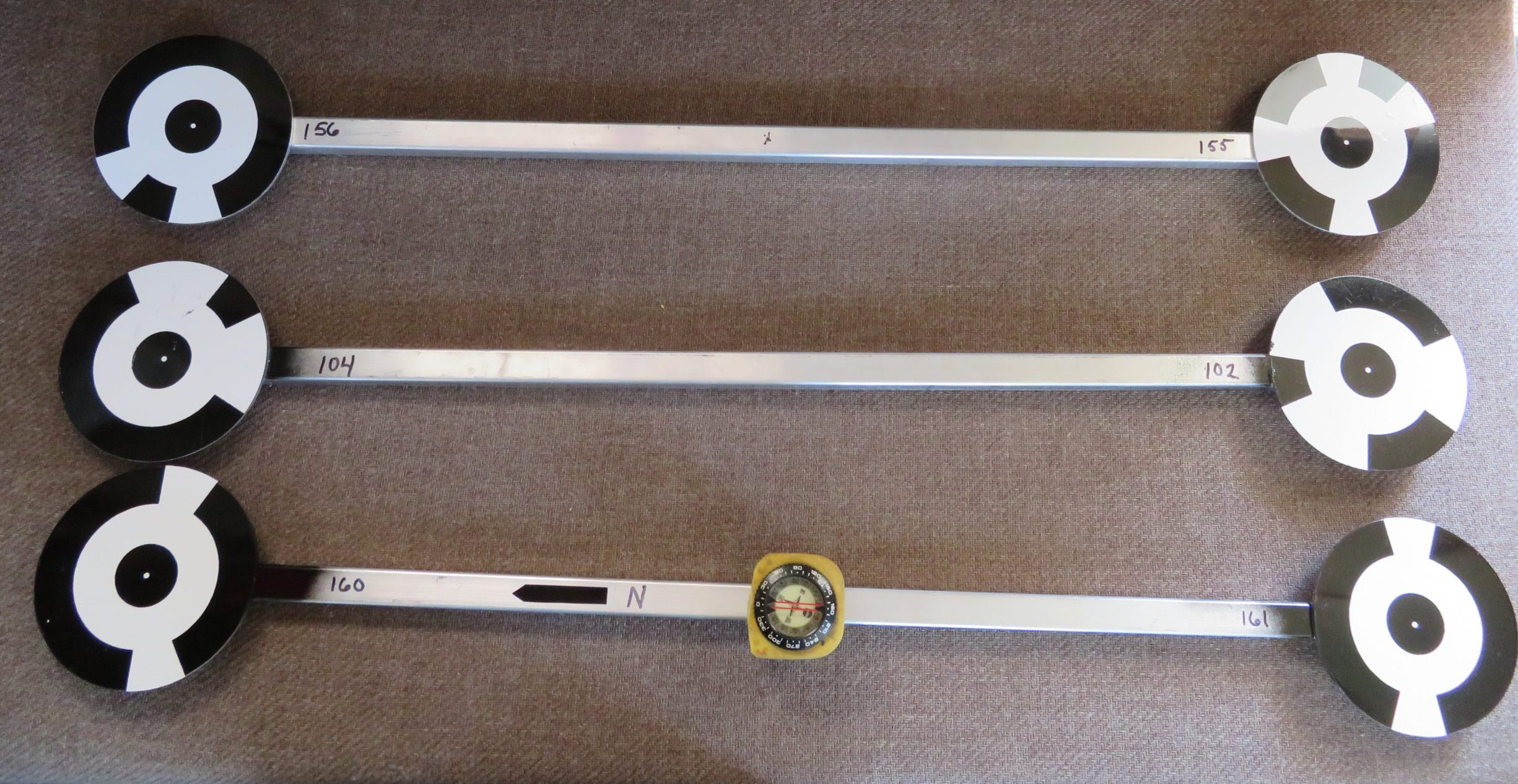
Example of markers we are using. Note the bottom marker has a compass so it can be oriented to show North in the site.
Post Processing Images: Images can be post processed. Tutorials suggest Lightroom for this but Photoshop also works well. It is good to minimize harsh shadows and strong highlights. If you color correct or exposure correct make one macro and apply it to all images so every image looks the same with respect to exposure and color. I have also used the local area corrections with some good success especially with artificial lighting on wrecks where the distance from the camera to the surfaces of the wreck varies considerably . One example where local area corrections helped considerably is on the model of the Barge Industry since the cabin was recessed a considerable distance from the edge of the deck. When I shot the corner edge of the deck to tie the sides of the hull to the deck the cabin was very much under exposed since it sat far from the edge of the deck.